|
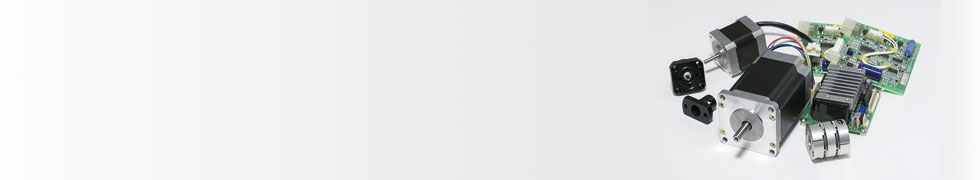
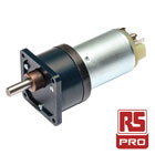
Brushless DC (BLDC) Motors
By Elvir Kahrimanovic, Senior Application System Engineer at Infineon.
From cordless power tools to industrial automation and from electric bikes to remote-controlled ‘drones’, an increasing number of motion control applications are now being built around the brushless DC (BLDC) motor. While BLDC solutions require more complex drive electronics than brushed alternatives, these motors offer a number of operational advantages that include higher efficiency and higher power density. This allows smaller, lighter and less expensive motors to be deployed. At the same time, there is less mechanical wear-and-tear, which leads to higher reliability, longer lifetimes and eliminates need for ongoing maintenance. BLDC motors also operate with lower audible and electrical noise than their brushed counterparts.
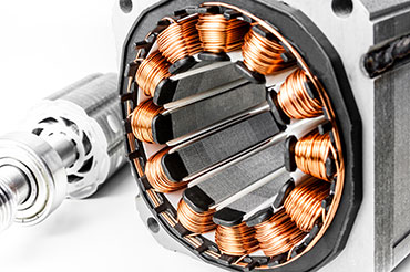
Sometimes referred to as an electronically commutated motor (ECM), a typical BLDC motor has a three-phase stator which keeps turning the rotor via an electronic control scheme that incorporates a three-phase inverter circuit. This circuit continually switches currents in the stator windings in synch with the rotor position which can be ascertained via sensors or through calculations based on the back electromotive force (EMF) at any particular moment. The flux generated in the stator interacts with the rotor flux, which defines the torque and the speed of the motor.
When designing a BLDC application, engineers can choose between using discrete components or integrated semiconductors that bring together a number of important drive and control functionalities into a single device.
Get in-depth information in Infineon’s white paper: Power Loss and Optimised MOSFET Selection in BLDC Motor Inverter Designs available via DesignSpark.
Keep reading to find out about other motor types – Brushed DC and AC motors.
Around 45% of our global energy consumption is from the operation of motors (World Energy Council: 2013 Survey Summary). They are a power-hungry but essential part of our daily lives and are found everywhere from small residential uses, such as household appliances and tools, through electric cars and trains in the transportation sector, right up to the largest industrial motors for offshore oil rigs and damns.
Since the industrial revolution we have been reducing time and labour by powering anything that we possibly could with a motor. A mass of electrically-powered devices have made our home lives easier and more convenient and our workplaces more efficient and profitable. But at what cost?
Energy-eating motors and the environment
In our modern world of diminishing fossil fuels, amidst fears for our ecology and environment, manufacturers of any goods driven by motors face challenging times ahead. With no wide-scale alternatives yet derived from renewable energy sources, the problem is exacerbated by an increase in demand coming from growing economic development in Africa, Asia and South America, coupled with our rapidly expanding global population.
Around the world, governments have been putting increasing legislative measures into place to reduce energy consumption for some years and these are only set to increase further. In addition, consumers in a retail sense are far smarter and look for low energy-consuming products routinely; the same is true for industrial customers looking to invest in more efficient equipment.
Miniaturising motors
In addition to minimising power usage, engineers are also challenged with squeezing motors, drives and their controllers into increasingly smaller dimensions. A washing machine that features a larger drum capacity offers a value-adding selling point to the customer, but it still needs to fit within standard dimensions. Reducing space for electronic components creates thermal management issues which pose further design challenges for engineers. Adding cooling mechanisms will only increase power consumption, so the motors themselves need to be engineered with improved efficiency levels so less heat is generated in the first place.
Motor Control Architecture
Motor Control Systems
The above diagram shows the building blocks of a typical motor control system depending on the type of motor, application, level of control and, if any, monitoring that is required.
Controller - Typically a microcontroller or DSP. This takes commands such as direction, speed and torque, which it uses to generate one or more signals to drive the motor, usually PWM. The controller may also be provided with feedback in the form of current and position sensing, in order to provide more accurate control, motor protection and failure detection.
Driver - More often than not a driver is required to amplify the signals generated by the controller in order to deliver sufficient power to the motor.
Sensors - A shunt or hall effect device may be used to measure the actual current supplied, thereby providing feedback. Actual motor position feedback may also be provided via an inductive or hall effect sensor, or encoder. This feedback can then be used to implement more sophisticated “closed loop” control providing actual information around the motor to better control the output.
Filtering - Filtering is generally employed at numerous points within a motor control system to suppress sources of Electromagnetic Interference (EMI). Types of filtering include ferrite cores and inductors.
Isolation - Galvanic isolation is generally used to isolate the motor controller from the rest of the system, which may be sensitive to transients and could also be at a different earth potential.
Open and Closed Loop Motors
To explain this in its most basic and simple context, an open loop system does not incorporate any feedback. The speed of the motor is controlled to a set point which can vary under different load conditions.
A closed loop system incorporates feedback by returning information to the input stage to adjust itself. So when speed is controlled to a set point and the load changes, the controller will adjust the speed back to the set point; a good example of this is a positional motor on a telescope which will constantly readjust itself to track the required co-ordinates.
Motor Control Featured Products
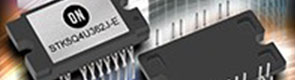
Building a more compact, reliable and efficient motor drive using ON Semiconductor Integrated Power Modules.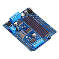
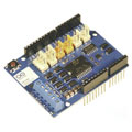
Arduino Motor/Stepper/Servo Shield
Manufacturer: Arduino
Manufacturer: Arduino
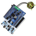
P-NUCLEO-IHM001, Motor Control Nucleo Pack
Manufacturer: ST Microelectronics
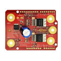
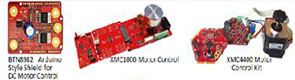
DC Motor Control Shield with BTN8982TA.
Manufacturer: Infineon
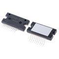
Manufacturer: ON Semiconductor
Power MOSFET, IXYS HiPerFET™ X2 Series
Manufacturer: IXYS
Manufacturer: Wolfspeed
Braccio - Arduino Controlled Robotic Arm
Manufacturer: Arduino
PICDEM™ Mechatronics Demonstration Kit
Manufacturer: Microchip
HARTING Han B Series Industrial Connectors
Manufacturer: HARTING

M23 SPEEDCON Hybrid Connectors
Manufacturer: Phoenix Contact
WE-CNSW SMD Common Mode Line Filter
Manufacturer: Würth Elektronik
Manufacturer: Murata
WE-MPSB EMI Multilayer Power Suppression Bead
Manufacturer: Würth Elektronik
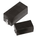
TE Connectivity Power Resistors
Manufacturer: TE Connectivity
Vishay K...H Series High Temperature MLCCs
Manufacturer: Vishay
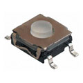
KSC Series IP67 Tactile Switches
Manufacturer: C&K
Manufacturer: TE Connectivity
Manufacturer: EPCOS
Motor Control Featured Brands


Additional Motor Control Resources

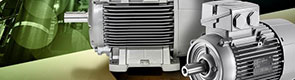


Motor Types
Electric motors basically use magnetism to create motion. There are two main categories of motors: AC (alternating current) and DC (direct current).
DC motors were the first to be invented and are still the simplest form of motors. DC motors are driven by passing a flow of current through a conductor inside a magnetic field to produce rotating torque. Main types of DC motors are Brushed DC and Brushless DC, with brushed motors generating power by connecting opposite poles of a power source to deliver negative and positive charges to the commutator when it makes physical contact with the brushes.
As the name suggests, brushless motors have no brushes, instead, permanent magnets are mounted around the perimeter of the motor. This eliminates the need for commutators and connections, as well as brushes. Brushed motors are simple and lower cost, but require more maintenance as the brushes need regular cleaning and replacement. Brushless motors on the other hand tend to be more accurate for applications that require controlled positioning, and have the added benefit of requiring little or no maintenance. This comes at a price however, as brushless motors cost more to manufacture and require a motor controller which could cost as much as the motor itself.
AC motors can also be categorised into two main types: Induction and Synchronous; with a third, less common type – Linear AC motors.
At a very basic level, AC motors consist of two primary parts: the outside part of the motor is known as the stator – the stationary part of the motor – which has coils that are supplied with alternating current to produce a rotating magnetic field; inside the rotor conects to a shaft which produces another rotating magnetic field. Linear motors are similar in principle to rotating motors but are configured with moving and stationary parts in a straight line – ultimately, instead of rotation, this produces linear motion.
Induction motors are named as such because torque is produced using electromagnetic induction. These are commonly known as squirrel cage or wound rotor motors.
Synchronous motors differ from induction motors in that they operate in precise synchronisation with line frequency. In contrast, induction motors rely on inducting current to produce magnetic field and require some ‘slip’ (slightly slower rotations) to actually induce current.
What to look for when choosing a motor
When selecting a motor there are a number of key attributes to look out for:
| Speed: | What speed do you need the motor to run at? This will determine your required speed control type. Do you need a range of ramp up times? |
|---|---|
| Torque: | Is a measure of the rotational turning force usually measured in Nm (newton metre) |
| Integral gearboxes: | Integral gearboxes work to reduce speed and increase torque. |
| Power requirement: | What power rating do you need? Is it for full load, normal load or light load? |
| Power rating: | Generally rated in watt (W) or horsepower (hp). Check normal operation and overload ratings. |
| Supply: | Check power supply requirements: voltage and current or specific controllers. |
| Mechanical configuration: | Motor size and dimensions will be dictated by the application it is for. Overall size, shaft size, mounting points and weight all need to be considered. |

Motor Control Product Links
- AC Geared Motors
- AC Motors
- DC Geared Motors
- DC Motors
- Ferrite cores
- IGBT Transistors
- IGBT Transistor Modules
- Inductors
- Motor Driver ICs
- MOSFET Power Drivers
- MOSFET Transistors
- Panel mount fixed resistors (shunt)
- Passive filters
- Power connectors
- Processor and Microcontroller Development Kits
- Rectifiers & Schottky Diodes
- Switches